Introduction
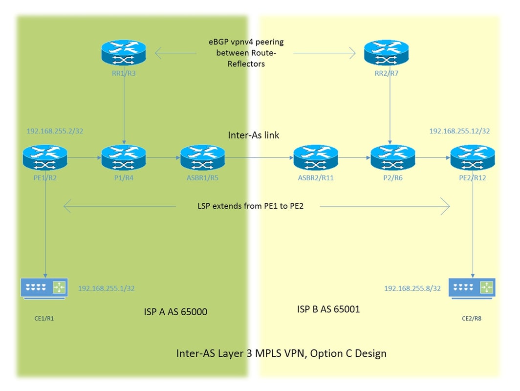
This document describes how to configure and verify the Inter-AS Layer 3 Multiprotocol Label Switching (MPLS) VPN, option C feature. A sample network scenario and its configuration and outputs are shown for a better understanding.
本文描述的是根据思科网站一篇配置文档(https://www.cisco.com/c/en/us/support/docs/multiprotocol-label-switching-mpls/mpls/200523-Configuration-and-Verification-of-Layer.html#)修改搭建的一个实验。
环境
- 模拟器:PNET 4.2.10
- Cisco IOL: l3-ADVENTERPRISEK9-M-15.4-2T.bin
配置
网络拓扑
网站原图
搭建的拓扑
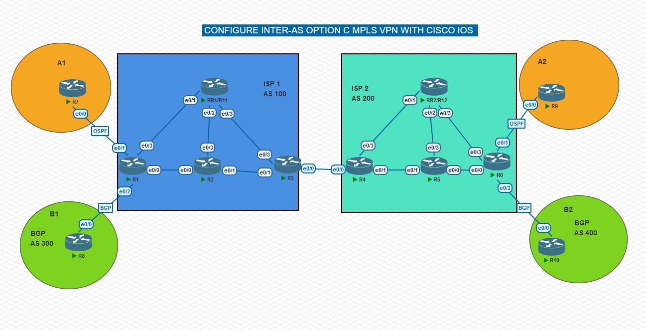
拓扑规划
- 每台路由配置环回接口 0 ,格式为 R1: 1.1.1.1/32
- 互联接口为:设备编号1 + 设备编号2 + .1.1 + 设备编号1,例如 R1 e0/0 接口IP地址:12.1.1.1/24
- R7、R8、R9、R10 为 CE,R11 和 R12 为 反射器
- ISP1,ISP2 底层 IGP 运行 OSPF 协议
- A1,A2 的 CE 与 PE 运行 OSPF 协议
- B1,B2 的 CE 与 PE 运行 BGP 协议
配置思路
- 配置 ISP 底层 OSPF IGP ,验证:show ip os nei / show ip route ospf
- 配置 ISP 启用 MPLS LDP,验证:show mpls interface / show mpls ldp discovery
- 配置 PE VRF,配置与 CE 互联接口划分到 VRF,验证:show ip vrf int / show ip route vrf X
- 配置 ISP 的 BGP 邻居,验证:show ip b summ / show ip b vpnv4 all summ
- 配置 RR1 和 RR2 的 MP-eBGP,验证:show ip b vpnv4 all summ
- 配置 CE 和 PE 间的路由协议,验证:show ip route vrf X / show ip os nei / show ip b summ
- 配置 PE 上 双向重分布
配置步骤
配置 IP 地址 (略)
配置 ISP 底层 IGP (以 ISP 1 为例,ISP2 同理)
!--- R1 commands.

int ran e 0/0,e0/3,lo0
 ip os 100 a 0

!--- R2 commands.

int ran e0/0-1,e0/3,lo0
 ip os 100 a 0

!--- R3 commands.

int ran e 0/1,e0/3,lo0
 ip os 100 a 0

!--- R11 commands.

int ran e 0/1-3,lo0
 ip os 100 a 0
**验证:**查看 OSPF 邻居,查看 OSPF 路由,以 R2 为例
!--- R2 output.

R2#sh ip os nei

Neighbor ID     Pri   State           Dead Time   Address         Interface
11.11.11.11       1   FULL/BDR        00:00:39    112.1.1.11      Ethernet0/3
3.3.3.3           1   FULL/DR         00:00:30    23.1.1.3        Ethernet0/1
1.1.1.1           1   FULL/BDR        00:00:39    12.1.1.1        Ethernet0/0

R2#sh ip route ospf | b Gate
Gateway of last resort is not set

      1.0.0.0/32 is subnetted, 1 subnets
O        1.1.1.1 [110/11] via 12.1.1.1, 02:06:04, Ethernet0/0
      3.0.0.0/32 is subnetted, 1 subnets
O        3.3.3.3 [110/11] via 23.1.1.3, 02:05:54, Ethernet0/1
      11.0.0.0/32 is subnetted, 1 subnets
O        11.11.11.11 [110/11] via 112.1.1.11, 02:05:54, Ethernet0/3
      111.0.0.0/24 is subnetted, 1 subnets
O        111.1.1.0 [110/20] via 12.1.1.1, 02:06:04, Ethernet0/0
      113.0.0.0/24 is subnetted, 1 subnets
O        113.1.1.0 [110/20] via 23.1.1.3, 02:05:54, Ethernet0/1
R2#
配置 ISP 启用 MPLS LDP (以 ISP 1 为例,ISP2 同理)
!--- R1 commands.

int ran e 0/0,e0/3
 mpls ip

!--- R2 commands.

int ran e0/0-1,e0/3
 mpls ip

!--- R3 commands.

int ran e 0/1,e0/3
 mpls ip

!--- R11 commands.

int ran e 0/1-3
 mpls ip
验证: 查看 LDP 接口和 ldp 会话,以 R2 为例
!--- R2 output.

R2#sh mpls interfaces
Interface              IP            Tunnel   BGP Static Operational
Ethernet0/0            Yes (ldp)     No       No  No     Yes
Ethernet0/1            Yes (ldp)     No       No  No     Yes
Ethernet0/3            Yes (ldp)     No       No  No     Yes
R2#sh mpls ldp dis
R2#sh mpls ldp discovery
 Local LDP Identifier:
    2.2.2.2:0
    Discovery Sources:
    Interfaces:
        Ethernet0/0 (ldp): xmit/recv
            LDP Id: 1.1.1.1:0
        Ethernet0/1 (ldp): xmit/recv
            LDP Id: 3.3.3.3:0
        Ethernet0/3 (ldp): xmit/recv
            LDP Id: 11.11.11.11:0
R2#
配置 PE 的 VRF,配置与 CE 互联的接口划分到 VRF
!--- R1 commands.

ip vrf a
 rd 7:100
 route-target export 7:7
 route-target import 9:9
ip vrf b
 rd 8:100
 route-target export 8:8
 route-target import 10:10

!
interface Ethernet0/1
 ip vrf forwarding a
 ip address 17.1.1.1 255.255.255.0

interface Ethernet0/2
 ip vrf forwarding b
 ip address 18.1.1.1 255.255.255.0

!--- R6 commands.

ip vrf a
 rd 9:200
 route-target export 9:9
 route-target import 7:7
ip vrf b
 rd 10:200
 route-target export 10:10
 route-target import 8:8

interface Ethernet0/1
 ip vrf forwarding a
 ip address 69.1.1.6 255.255.255.0
!
interface Ethernet0/2
 ip vrf forwarding b
 ip address 106.1.1.6 255.255.255.0
**验证:**查看 VRF 路由表,以 R1 为例
!--- R1 output.

R1#sh ip route vrf a | b Gate
Gateway of last resort is not set

      7.0.0.0/32 is subnetted, 1 subnets
O        7.7.7.7 [110/11] via 17.1.1.7, 02:15:47, Ethernet0/1
      17.0.0.0/8 is variably subnetted, 2 subnets, 2 masks
C        17.1.1.0/24 is directly connected, Ethernet0/1
L        17.1.1.1/32 is directly connected, Ethernet0/1
R1#
R1#sh ip route vrf b | b Gate
Gateway of last resort is not set

      8.0.0.0/32 is subnetted, 1 subnets
B        8.8.8.8 [20/0] via 18.1.1.8, 02:16:08
      18.0.0.0/8 is variably subnetted, 2 subnets, 2 masks
C        18.1.1.0/24 is directly connected, Ethernet0/2
L        18.1.1.1/32 is directly connected, Ethernet0/2
R1#
配置 ISP 的 BGP 邻居
R3 与 R4 配置 IPv4 BGP 邻居,R3 宣告 1.1.1.1 和 11.11.11.11,R4 宣告 6.6.6.6 和 12.12.12.12
将 BGP 路由重分布进底层 OSPF 协议,为了学习到对端 RR 和 PE 路由,建立 MP-BGP 需要
由于底层 OSPF 协议的运行,R3 与 R4 已经学习到这些路由,在建立 eBGP 邻居后能传递到对端
!--- R3 commands.

router bgp 100
 bgp log-neighbor-changes
 network 1.1.1.1 mask 255.255.255.255
 network 11.11.11.11 mask 255.255.255.255
 neighbor 34.1.1.4 remote-as 200
 neighbor 34.1.1.4 send-label

router ospf 100
 redistribute bgp 100 subnets

!--- R4 commands.

router bgp 200
 bgp log-neighbor-changes
 network 6.6.6.6 mask 255.255.255.255
 network 12.12.12.12 mask 255.255.255.255
 neighbor 34.1.1.3 remote-as 100
 neighbor 34.1.1.3 send-label

router ospf 200
 redistribute bgp 200 subnets
验证:
R3 与 R4 的 eBGP 邻居
R3#sh ip b summary
BGP router identifier 3.3.3.3, local AS number 100
BGP table version is 75, main routing table version 75
4 network entries using 560 bytes of memory
4 path entries using 320 bytes of memory
4/4 BGP path/bestpath attribute entries using 576 bytes of memory
1 BGP AS-PATH entries using 24 bytes of memory
0 BGP route-map cache entries using 0 bytes of memory
0 BGP filter-list cache entries using 0 bytes of memory
BGP using 1480 total bytes of memory
BGP activity 4/0 prefixes, 36/32 paths, scan interval 60 secs

Neighbor        V           AS MsgRcvd MsgSent   TblVer  InQ OutQ Up/Down  State/PfxRcd
34.1.1.4        4          200      90      90       75    0    0 01:16:45        0
R1 的 1.1.1.1 去往 R6 的 6.6.6.6 路由可达,标签路径连续
R11 的 11.11.11.11 去往 R12 的 12.12.12.12 路由可达,标签路径连续
R1#ping  6.6.6.6 source 1.1.1.1
Type escape sequence to abort.
Sending 5, 100-byte ICMP Echos to 6.6.6.6, timeout is 2 seconds:
Packet sent with a source address of 1.1.1.1
!!!!!
Success rate is 100 percent (5/5), round-trip min/avg/max = 6/6/8 ms
R1#traceroute 6.6.6.6 source 1.1.1.1
Type escape sequence to abort.
Tracing the route to 6.6.6.6
VRF info: (vrf in name/id, vrf out name/id)
  1 12.1.1.2 [MPLS: Label 24 Exp 0] 5 msec 6 msec 6 msec
  2 23.1.1.3 [MPLS: Label 26 Exp 0] 6 msec 5 msec 6 msec
  3 34.1.1.4 [MPLS: Label 27 Exp 0] 7 msec 7 msec 5 msec
  4 45.1.1.5 [MPLS: Label 22 Exp 0] 4 msec 5 msec 6 msec
  5 56.1.1.6 6 msec *  7 msec
R1#
----------------------------------------------------------
R11#ping 12.12.12.12 source 11.11.11.11
Type escape sequence to abort.
Sending 5, 100-byte ICMP Echos to 12.12.12.12, timeout is 2 seconds:
Packet sent with a source address of 11.11.11.11
!!!!!
Success rate is 100 percent (5/5), round-trip min/avg/max = 3/3/4 ms
R11#trace 12.12.12.12 source 11.11.11.11
Type escape sequence to abort.
Tracing the route to 12.12.12.12
VRF info: (vrf in name/id, vrf out name/id)
  1 113.1.1.3 [MPLS: Label 27 Exp 0] 4 msec 4 msec 4 msec
  2 34.1.1.4 [MPLS: Label 25 Exp 0] 3 msec 2 msec 2 msec
  3 124.1.1.12 4 msec *  4 msec
R11#
关于send-label 命令:
tell the router to send the lables of bgp prefix to its peer,为 BGP 路由传递标签,使用此命令后,对应接口自动配置 mpls bgp forwarding ,但是 no 掉后接口的这行配置并不会自动去掉
*Mar 4 05:54:10.850: %BGP_LMM-6-AUTOGEN1: The mpls bgp forwarding command has been configured on interface: Ethernet0/0未配置 send-label 命令前,R3 去往 6.6.6.6 的标签 是空标签,R3 的动作是弹出所有标签,标签中断。
R3#sh mpls forwarding-table 6.6.6.6
Local      Outgoing   Prefix           Bytes Label   Outgoing   Next Hop
Label      Label      or Tunnel Id     Switched      interface
26         No Label   6.6.6.6/32       0             Et0/0      34.1.1.4
R3#sh ip b la
R3#sh ip b labels
   Network          Next Hop      In label/Out label
   1.1.1.1/32       23.1.1.2        nolabel/nolabel
   6.6.6.6/32       34.1.1.4        nolabel/nolabel
   11.11.11.11/32   113.1.1.11      nolabel/nolabel
   12.12.12.12/32   34.1.1.4        nolabel/nolabel

R3#sh ip b 6.6.6.6
BGP routing table entry for 6.6.6.6/32, version 66
Paths: (1 available, best #1, table default)
  Not advertised to any peer
  Refresh Epoch 1
  200
    34.1.1.4 from 34.1.1.4 (4.4.4.4)
      Origin IGP, metric 21, localpref 100, valid, external, best
      rx pathid: 0, tx pathid: 0x0
R3#
配置 send-label 命令后,分配 27 标签
R3#sh mpls forwarding-table 6.6.6.6
Local      Outgoing   Prefix           Bytes Label   Outgoing   Next Hop
Label      Label      or Tunnel Id     Switched      interface
26         27         6.6.6.6/32       0             Et0/0      34.1.1.4
R3#sh ip b labels
   Network          Next Hop      In label/Out label
   1.1.1.1/32       23.1.1.2        21/nolabel
   6.6.6.6/32       34.1.1.4        nolabel/27
   11.11.11.11/32   113.1.1.11      25/nolabel
   12.12.12.12/32   34.1.1.4        nolabel/25

R3#sh ip b 6.6.6.6
BGP routing table entry for 6.6.6.6/32, version 56
Paths: (1 available, best #1, table default)
  Not advertised to any peer
  Refresh Epoch 1
  200
    34.1.1.4 from 34.1.1.4 (4.4.4.4)
      Origin IGP, metric 21, localpref 100, valid, external, best
      mpls labels in/out nolabel/27
      rx pathid: 0, tx pathid: 0x0

# 在 R4 上查看到关于去往6.6.6.6 的 入向标签 27
R4#sh ip bgp labels
   Network          Next Hop      In label/Out label
   1.1.1.1/32       34.1.1.3        nolabel/21
   6.6.6.6/32       45.1.1.5        27/nolabel
   11.11.11.11/32   34.1.1.3        nolabel/25
   12.12.12.12/32   124.1.1.12      25/nolabel

R4#
R1 与 R11 配置 BGP VPNV4 邻居
注意:R3 与 R11 不建立 BGP 邻居
!--- R1 commands.

router bgp 100
 no bgp default ipv4-unicast
 neighbor 11.11.11.11 remote-as 100
 neighbor 11.11.11.11 update-source Loopback0

 address-family vpnv4
  neighbor 11.11.11.11 activate

!--- R11 commands.

router bgp 100
 bgp log-neighbor-changes
 no bgp default ipv4-unicast
 neighbor 1.1.1.1 remote-as 100
 neighbor 1.1.1.1 update-source Loopback0

 address-family vpnv4
  neighbor 1.1.1.1 activate
  neighbor 1.1.1.1 route-reflector-client
R6 与 R12 配置 BGP VPNV4 邻居
注意:R4 与 R12 不建立 BGP 邻居
!--- R6 commands.

router bgp 200
 no bgp default ipv4-unicast
 neighbor 12.12.12.12 remote-as 200
 neighbor 12.12.12.12 update-source Loopback0

 address-family vpnv4
  neighbor 12.12.12.12 activate

!--- R12 commands.

router bgp 200
 no bgp default ipv4-unicast
 neighbor 6.6.6.6 remote-as 200
 neighbor 6.6.6.6 update-source Loopback0

 address-family vpnv4
  neighbor 6.6.6.6 activate
  neighbor 6.6.6.6 route-reflector-client
**验证:**VPNV4 邻居
sh ip b vpnv4 all summaryR11 与 R12 建立 MP-eBGP 邻居
设置 eBGP 多跳。不是物理直连的 eBGP 邻居
设置下一跳不改变。R11 与 R12 建立 MP-eBGP 邻居,传递路由时默认下一跳改变成自身,这样 ISP 两侧的流量互通都流经反射器不合理,设置下一跳不改变后,R1 上去往 ISP2 CE 的路由下一跳看到的是 R6 的 6.6.6.6 ,最后再在两个 ISP 内部控制底层 IGP 的路径,使得流量不经过反射器。
!--- R11 commands.

router bgp 100
 neighbor 12.12.12.12 remote-as 200
 neighbor 12.12.12.12 ebgp-multihop 255
 neighbor 12.12.12.12 update-source Loopback0

 address-family vpnv4
  neighbor 12.12.12.12 activate
  neighbor 12.12.12.12 next-hop-unchanged

!--- R12 commands.

router bgp 200
 neighbor 11.11.11.11 remote-as 100
 neighbor 11.11.11.11 ebgp-multihop 255
 neighbor 11.11.11.11 update-source Loopback0

 address-family vpnv4
  neighbor 11.11.11.11 activate
  neighbor 11.11.11.11 next-hop-unchanged
验证:查看 R11 上的 BGP 邻居
R11#sh ip b vpnv4 all summary
BGP router identifier 11.11.11.11, local AS number 100
BGP table version is 67, main routing table version 67
6 network entries using 912 bytes of memory
6 path entries using 480 bytes of memory
5/5 BGP path/bestpath attribute entries using 760 bytes of memory
3 BGP AS-PATH entries using 72 bytes of memory
4 BGP extended community entries using 128 bytes of memory
0 BGP route-map cache entries using 0 bytes of memory
0 BGP filter-list cache entries using 0 bytes of memory
BGP using 2352 total bytes of memory
BGP activity 6/0 prefixes, 6/0 paths, scan interval 60 secs

Neighbor        V           AS MsgRcvd MsgSent   TblVer  InQ OutQ Up/Down  State/PfxRcd
1.1.1.1         4          100     127     151       67    0    0 01:50:57        3
12.12.12.12     4          200     190     185       67    0    0 01:50:16        3
R11#
配置 CE 和 PE 间的路由协议
以 R7,R8,R1 为例, R9,R10,R6 同理
!--- R7 commands.

int ran e 0/0,lo0
 ip os 7 a 0

!--- R8 commands.

router bgp 300
 network 8.8.8.8 mask 255.255.255.255
 neighbor 18.1.1.1 remote-as 100

!--- R1 commands.

router ospf 1 vrf a
 router-id 1.1.1.17
 network 17.1.1.1 0.0.0.0 area 0

router bgp 100
 address-family ipv4 vrf b
  neighbor 18.1.1.8 remote-as 300
验证:
show ip os nei
show ip route ospf
show ip route vrf a
show ip route vrf b

sh ip b summary
配置 PE 上 双向重分布
以 R1 为例,只需在 VRF a
!--- R1 commands.
# 只需在 vrf a 和 BGP ipv4 vrf a 视图下配置重分布
# R8 - R1 之间运行的是 BGP ,在 BGP ipv4 vrf b 视图下建立邻居即可

router ospf 1 vrf a
 redistribute bgp 100 subnets

router bgp 100
 address-family ipv4 vrf a
  redistribute ospf 1
优化ISP 内部 OSPF 下一跳
查看 R1 路由表发现,去往 9.9.9.9 下一跳是 6.6.6.6
R1#sh ip b vpnv4 vrf a
BGP table version is 166, local router ID is 1.1.1.1
Status codes: s suppressed, d damped, h history, * valid, > best, i - internal,
              r RIB-failure, S Stale, m multipath, b backup-path, f RT-Filter,
              x best-external, a additional-path, c RIB-compressed,
Origin codes: i - IGP, e - EGP, ? - incomplete
RPKI validation codes: V valid, I invalid, N Not found

     Network          Next Hop            Metric LocPrf Weight Path
Route Distinguisher: 7:100 (default for vrf a)
 *>  7.7.7.7/32       17.1.1.7                11         32768 ?
 *>i 9.9.9.9/32       6.6.6.6                  0    100      0 200 ?
 *>  17.1.1.0/24      0.0.0.0                  0         32768 ?
 *>i 69.1.1.0/24      6.6.6.6                  0    100      0 200 ?
R1#
R1#sh ip route vrf a  | b Gate
Gateway of last resort is not set

      7.0.0.0/32 is subnetted, 1 subnets
O        7.7.7.7 [110/11] via 17.1.1.7, 04:21:39, Ethernet0/1
      9.0.0.0/32 is subnetted, 1 subnets
B        9.9.9.9 [200/0] via 6.6.6.6, 03:10:42
      17.0.0.0/8 is variably subnetted, 2 subnets, 2 masks
C        17.1.1.0/24 is directly connected, Ethernet0/1
L        17.1.1.1/32 is directly connected, Ethernet0/1
      69.0.0.0/24 is subnetted, 1 subnets
B        69.1.1.0 [200/0] via 6.6.6.6, 03:10:42
R1#
再查找,去往 6.6.6.6 前缀有两条路径,管理和开销都一致,负载均衡?
这条路由是 R3 BGP 重分布进底层 IGP OSPF 而学习到的,有两条路径,管理距离110,metric 1 ,这时候需要比较forwarding metric,很不巧的是forwarding metric 也是一样,这样去往 6.6.6.6 就真负载均衡。forwarding metric 是本地到 ASBR 的 开销,修改 R11 e0/1-3 的开销。同理也需要修改 R12 的接口开销。
O E2     12.12.12.12/32 [110/1] via 111.1.1.11, 01:37:27, Ethernet0/3
                        [110/1] via 12.1.1.2, 03:15:27, Ethernet0/0
R1#sh ip route | b Gate Gateway of last resort is not set 1.0.0.0/32 is subnetted, 1 subnets C 1.1.1.1 is directly connected, Loopback0 2.0.0.0/32 is subnetted, 1 subnets O 2.2.2.2 [110/11] via 12.1.1.2, 04:26:59, Ethernet0/0 3.0.0.0/32 is subnetted, 1 subnets O 3.3.3.3 [110/21] via 111.1.1.11, 01:37:27, Ethernet0/3 [110/21] via 12.1.1.2, 04:26:49, Ethernet0/0 6.0.0.0/32 is subnetted, 1 subnets O E2 6.6.6.6 [110/1] via 111.1.1.11, 01:37:27, Ethernet0/3 [110/1] via 12.1.1.2, 03:15:27, Ethernet0/0 …… R1# R1#sh ip route 6.6.6.6 Routing entry for 6.6.6.6/32 Known via "ospf 100", distance 110, metric 1 Tag 200, type extern 2, forward metric 20 Last update from 12.1.1.2 on Ethernet0/0, 00:00:51 ago Routing Descriptor Blocks: * 111.1.1.11, from 3.3.3.3, 00:31:15 ago, via Ethernet0/3 Route metric is 1, traffic share count is 1 Route tag 200 12.1.1.2, from 3.3.3.3, 00:00:51 ago, via Ethernet0/0 Route metric is 1, traffic share count is 1 Route tag 200 R1## 修改 R11 R12 的接口开销 R11(config)#int ran e 0/1-/3 R11(config-if-range)#ip ospf cost 1000 R12(config-if)#int ran e 0/1-0/3 R12(config-if-range)#ip ospf cost 1000# 修改 R11 R12 的接口开销后 R1#sh ip route 6.6.6.6 Routing entry for 6.6.6.6/32 Known via "ospf 100", distance 110, metric 1 Tag 200, type extern 2, forward metric 20 Last update from 12.1.1.2 on Ethernet0/0, 00:08:51 ago Routing Descriptor Blocks: * 12.1.1.2, from 3.3.3.3, 00:08:51 ago, via Ethernet0/0 Route metric is 1, traffic share count is 1 Route tag 200 R1# R6#sh ip rou 1.1.1.1 Routing entry for 1.1.1.1/32 Known via "ospf 200", distance 110, metric 1 Tag 100, type extern 2, forward metric 20 Last update from 56.1.1.5 on Ethernet0/0, 00:02:30 ago Routing Descriptor Blocks: * 56.1.1.5, from 4.4.4.4, 00:39:02 ago, via Ethernet0/0 Route metric is 1, traffic share count is 1 Route tag 100 R6#
测试
R7 和 R9 之间的 ping 操作
R7#ping 9.9.9.9 source 7.7.7.7
Type escape sequence to abort.
Sending 5, 100-byte ICMP Echos to 9.9.9.9, timeout is 2 seconds:
Packet sent with a source address of 7.7.7.7
!!!!!
Success rate is 100 percent (5/5), round-trip min/avg/max = 8/8/11 ms
R7#
R9#ping 7.7.7.7 source 9.9.9.9
Type escape sequence to abort.
Sending 5, 100-byte ICMP Echos to 7.7.7.7, timeout is 2 seconds:
Packet sent with a source address of 9.9.9.9
!!!!!
Success rate is 100 percent (5/5), round-trip min/avg/max = 8/8/10 ms
R9#
R8 和 R10 之间的 ping 操作
R8#ping 10.10.10.10 source 8.8.8.8
Type escape sequence to abort.
Sending 5, 100-byte ICMP Echos to 10.10.10.10, timeout is 2 seconds:
Packet sent with a source address of 8.8.8.8
!!!!!
Success rate is 100 percent (5/5), round-trip min/avg/max = 8/9/13 ms
R8#
R10#ping 8.8.8.8 source 10.10.10.10
Type escape sequence to abort.
Sending 5, 100-byte ICMP Echos to 8.8.8.8, timeout is 2 seconds:
Packet sent with a source address of 10.10.10.10
!!!!!
Success rate is 100 percent (5/5), round-trip min/avg/max = 8/9/10 ms
R10#
R7 和 R9 之间的 Traceroute 操作
R7#traceroute 9.9.9.9 source 7.7.7.7
Type escape sequence to abort.
Tracing the route to 9.9.9.9
VRF info: (vrf in name/id, vrf out name/id)
  1 17.1.1.1 1 msec 1 msec 2 msec
  2 12.1.1.2 [MPLS: Labels 24/26 Exp 0] 8 msec 8 msec 8 msec
  3 23.1.1.3 [MPLS: Labels 26/26 Exp 0] 8 msec 12 msec 7 msec
  4 34.1.1.4 [MPLS: Labels 27/26 Exp 0] 8 msec 9 msec 8 msec
  5 45.1.1.5 [MPLS: Labels 22/26 Exp 0] 9 msec 8 msec 8 msec
  6 69.1.1.6 [MPLS: Label 26 Exp 0] 9 msec 7 msec 9 msec
  7 69.1.1.9 9 msec *  9 msec
R7#
R9#traceroute 7.7.7.7 source 9.9.9.9
Type escape sequence to abort.
Tracing the route to 7.7.7.7
VRF info: (vrf in name/id, vrf out name/id)
  1 69.1.1.6 2 msec 39 msec 2 msec
  2 56.1.1.5 [MPLS: Labels 25/26 Exp 0] 10 msec 9 msec 9 msec
  3 45.1.1.4 [MPLS: Labels 23/26 Exp 0] 12 msec 9 msec 9 msec
  4 34.1.1.3 [MPLS: Labels 21/26 Exp 0] 10 msec 8 msec 10 msec
  5 23.1.1.2 [MPLS: Labels 19/26 Exp 0] 9 msec 10 msec 11 msec
  6 17.1.1.1 [MPLS: Label 26 Exp 0] 7 msec 18 msec 9 msec
  7 17.1.1.7 8 msec *  8 msec
R9#
R8 和 R10 之间的 Traceroute 操作
R8#traceroute 10.10.10.10 source 8.8.8.8
Type escape sequence to abort.
Tracing the route to 10.10.10.10
VRF info: (vrf in name/id, vrf out name/id)
  1 18.1.1.1 2 msec 1 msec 1 msec
  2 12.1.1.2 [MPLS: Labels 24/28 Exp 0] 8 msec 9 msec 9 msec
  3 23.1.1.3 [MPLS: Labels 26/28 Exp 0] 9 msec 9 msec 9 msec
  4 34.1.1.4 [MPLS: Labels 27/28 Exp 0] 10 msec 8 msec 10 msec
  5 45.1.1.5 [MPLS: Labels 22/28 Exp 0] 7 msec 9 msec 8 msec
  6 106.1.1.6 [MPLS: Label 28 Exp 0] 8 msec 7 msec 9 msec
  7 106.1.1.10 8 msec *  10 msec
R8#
R10#traceroute 8.8.8.8 source 10.10.10.10
Type escape sequence to abort.
Tracing the route to 8.8.8.8
VRF info: (vrf in name/id, vrf out name/id)
  1 106.1.1.6 1 msec 2 msec 1 msec
  2 56.1.1.5 [MPLS: Labels 25/28 Exp 0] 8 msec 8 msec 11 msec
  3 45.1.1.4 [MPLS: Labels 23/28 Exp 0] 8 msec 28 msec 8 msec
  4 34.1.1.3 [MPLS: Labels 21/28 Exp 0] 8 msec 11 msec 8 msec
  5 23.1.1.2 [MPLS: Labels 19/28 Exp 0] 9 msec 8 msec 10 msec
  6 18.1.1.1 [MPLS: Label 28 Exp 0] 16 msec 6 msec 7 msec
  7 18.1.1.8 9 msec *  10 msec
R10#
一个视频
最后
- 文中可能有些配置未提及或内容术语表述的不规范,请见谅。
- 配置存阿里云盘了,这是链接:[分享的文件 ]
- 欢迎“
来电”来函探讨。