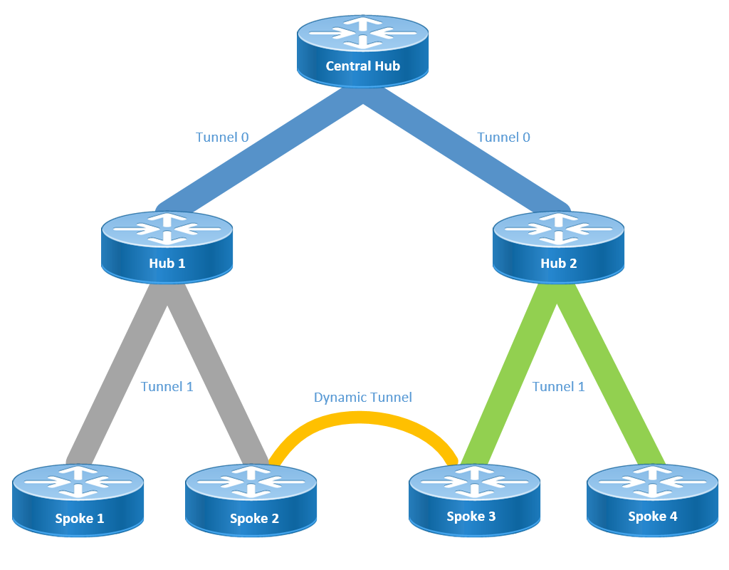
以前了解过DMVPN组网,没发现还有这么个分层组网的模型,于是玩一玩做个记录
华为的说法是Hub级联网络部署DSVPN
华为网站文档链接: https://support.huawei.com/enterprise/zh/doc/EDOC1100271739/baf3c434
一段蹩脚的Cisco网站机器翻译原文
分层设置(大于一级)允许更复杂的基于树的DMVPN网络拓扑。基于树的拓扑允许使用区域集线器构建DMVPN网络,区域集线器是中心集线器的分支。此体系结构允许区域中心处理其区域分支的数据和下一跳解析协议(NHRP)控制流量。但是,它仍允许在DMVPN网络内的任何分支之间构建分支到分支隧道,无论它们是否位于同一区域。此架构还允许DMVPN网络布局更紧密地匹配区域或分层数据流模式。
DMVPN的组成
- 多GRE隧道
- NHRP
- 动态路由协议
- IPSec加密
配置思路也是分这四个步骤,本人觉得DMVPN的精髓在于NHRP协议,这个协议可以使Spoke站点之间动态建立隧道,新增Spoke站点无须改动Hub端配置,看上去很智能哦
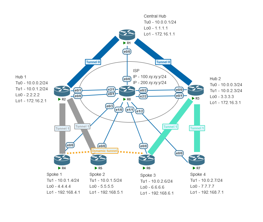
实验逻辑拓扑
实验物理拓扑
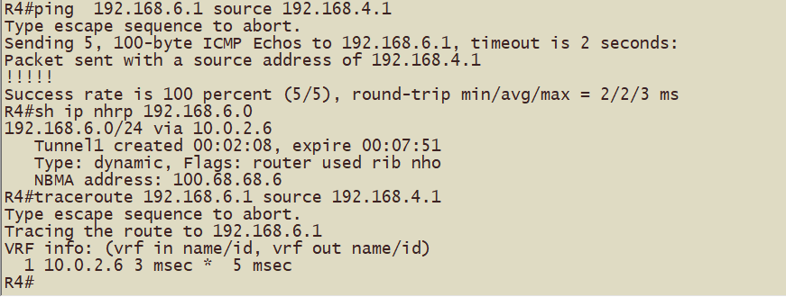
最终的效果(例如:R4的192.168.4.0/24网段去往R6的192.168.6.0/24网段一跳可达)
配置过程
基础配置
包括IP地址,去往ISP的默认路由等
基础配置完成后各Hub路由器和Spoke路由器可以ping通各个公网IP地址
R1#ping 100.28.28.2
Type escape sequence to abort.
Sending 5, 100-byte ICMP Echos to 100.28.28.2, timeout is 2 seconds:
..!!!
Success rate is 60 percent (3/5), round-trip min/avg/max = 4/5/7 ms
R1#ping 200.28.28.2
Type escape sequence to abort.
Sending 5, 100-byte ICMP Echos to 200.28.28.2, timeout is 2 seconds:
!!!!!
Success rate is 100 percent (5/5), round-trip min/avg/max = 2/2/3 ms
R1#ping 100.38.38.3
Type escape sequence to abort.
Sending 5, 100-byte ICMP Echos to 100.38.38.3, timeout is 2 seconds:
!!!!!
Success rate is 100 percent (5/5), round-trip min/avg/max = 2/2/4 ms
R1#ping 200.38.38.3
Type escape sequence to abort.
Sending 5, 100-byte ICMP Echos to 200.38.38.3, timeout is 2 seconds:
!!!!!
Success rate is 100 percent (5/5), round-trip min/avg/max = 2/2/4 ms
R1#ping 100.48.48.4
Type escape sequence to abort.
Sending 5, 100-byte ICMP Echos to 100.48.48.4, timeout is 2 seconds:
!!!!!
Success rate is 100 percent (5/5), round-trip min/avg/max = 2/3/5 ms
R1#ping 100.58.58.5
Type escape sequence to abort.
Sending 5, 100-byte ICMP Echos to 100.58.58.5, timeout is 2 seconds:
!!!!!
Success rate is 100 percent (5/5), round-trip min/avg/max = 2/3/4 ms
R1#ping 100.68.68.6
Type escape sequence to abort.
Sending 5, 100-byte ICMP Echos to 100.68.68.6, timeout is 2 seconds:
!!!!!
Success rate is 100 percent (5/5), round-trip min/avg/max = 2/2/4 ms
R1#ping 100.78.78.7
Type escape sequence to abort.
Sending 5, 100-byte ICMP Echos to 100.78.78.7, timeout is 2 seconds:
!!!!!
Success rate is 100 percent (5/5), round-trip min/avg/max = 2/3/4 ms
R1#ping 8.8.8.8
Type escape sequence to abort.
Sending 5, 100-byte ICMP Echos to 8.8.8.8, timeout is 2 seconds:
!!!!!
Success rate is 100 percent (5/5), round-trip min/avg/max = 1/1/2 ms
R1#
多GRE隧道
Central Hub 与 Hub1,Hub2 配置tunnel
mGRE与单GRE的配置区别在于隧道模式 multipoint 和填写远端destination地址
!配置R1,R2,R3的tunnel,注意修改tunnel的IP地址,R2,R3 如法炮制
!R1 Tunnel0 (R1)
interface Tunnel0
 ip address 10.0.0.1 255.255.255.0
 tunnel source Ethernet0/0
 tunnel mode gre multipoint
 tunnel key 12345
Hub1,Hub2 ,Spoke配置tunnel
在Hub1,Hub2上配置tunnel 1(与Spoke建立隧道使用)
! Hub1 Tunnel1 (R2)
interface Tunnel1
 ip address 10.0.1.2 255.255.255.0
 no ip redirects
 tunnel source Ethernet0/1
 tunnel mode gre multipoint
 tunnel key 12345

! Hub2 Tunnel1 (R3)
interface Tunnel1
 ip address 10.0.2.3 255.255.255.0
 no ip redirects
 tunnel source Ethernet0/1
 tunnel mode gre multipoint
 tunnel key 12345

! Spoke1 (R4)
interface Tunnel1
 ip address 10.0.1.4 255.255.255.0
 no ip redirects
 tunnel source Ethernet0/0
 tunnel mode gre multipoint
 tunnel key 12345

 ! 其他Spoke站点如法炮制
NHRP
Central Hub的配置(R1)
!Central Hub (R1)
interface Tunnel0
 ip nhrp authentication cisco # 配置nhrp认证(可选)
 ip nhrp map multicast dynamic # 动态接受组播映射,(Version 15.7(3)M2 版本默认开启)
 ip nhrp network-id 123 # network-id,很重要,当前这个拓扑需要同一配置,原因是影响nhrp解析请求的发送
 ip nhrp redirect # nhrp的重定向,Hub向spoke发送重定向消息
Hub1和Hub2的配置(以Hub1为例(R2))
! Hub 1 (R2)
interface Tunnel0
 ip nhrp authentication cisco
 ip nhrp map 10.0.0.1 100.18.18.1 # 隧道地址对应的公网地址映射
 ip nhrp map multicast 100.18.18.1 # 组播对应的公网地址映射
 ip nhrp network-id 123 # network-id,很重要,当前这个拓扑需要同一配置,原因是影响nhrp解析请求的发送
 ip nhrp nhs 10.0.0.1 # 配置nhs,spoke向nhs注册
 ip nhrp shorcut # Hub1和Hub2是Central Hub的Spoke (Version 15.7(3)M2 版本默认开启)
 ip nhrp redirect # 当前这个拓扑,需要配置这一项,因为在配置动态路由协议后,R3去往R4和R5业务网段的下一跳是R2

interface Tunnel1
 ip nhrp authentication cisco
 ip nhrp network-id 123
 ip nhrp redirect
Spoke1,2,3,4的配置(以Spoke1和Spoke3为例)
!Spoke 1 (R4)
interface Tunnel1
 ip nhrp authentication cisco
 ip nhrp map 10.0.1.2 200.28.28.2
 ip nhrp map multicast 200.28.28.2
 ip nhrp network-id 123
 ip nhrp nhs 10.0.1.2

!Spoke 3 (R6)
interface Tunnel1
 ip nhrp authentication cisco
 ip nhrp network-id 123
 ip nhrp nhs 10.0.2.3 nbma 200.38.38.3 multicast # 一次性配置nhs,映射地址
在配置完成mGRE和NHRP之后,产生流量之后(ping测试)应该可以观察到以下现象
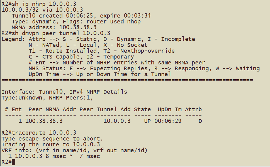
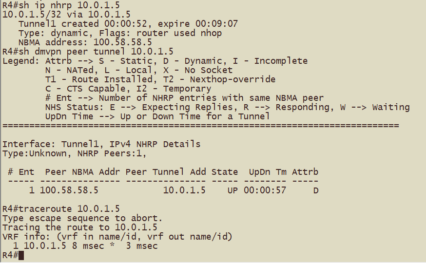
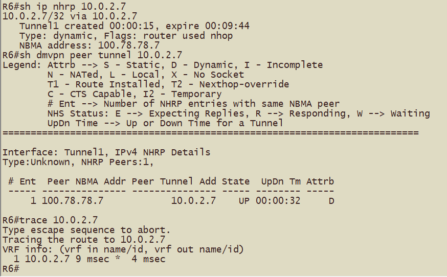
Hub1(R2)到Hub2(R3)的tunnel地址形成动态映射和动态隧道,跟踪路径查看到一跳可达
Spoke1(R4)到Spoke2(R5)的tunnel地址形成动态映射和动态隧道,跟踪路径查看到一跳可达
Spoke3(R6)到Spoke4(R7)的tunnel地址形成动态映射和动态隧道,跟踪路径查看到一跳可达
动态路由协议
可选的协议RIP、EIGRP、OSPF、BGP、ODR
本实验业务网络选用OSPF,Central Hub,Hub1和Hub2设计在Area0;Hub1和Spoke1,Spoke2设计在Area1;Hub2和Spoke3,Spoke4设计在Area2;
根据组网情况分析,OSPF的网络类型可选的有广播、点到多点;
本实验选用广播,因为在配置tunnel 的ospf网络类型为广播后,同一个hub下的spoke站点能学习到优化下一跳后的路由,注意修改Spoke的ospf优先级为0不参与DR选举;
(配置tunnel 的ospf网络类型为点到多点后,spoke站点在产生分支站点流量后会对路由进行override, % - next hop override ,O之后有%符号)
Central Hub,Hub1和Hub2的OSPF配置
!Central Hub (R1)
router ospf 110
 router-id 1.1.1.1
 network 10.0.0.1 0.0.0.0 area 0
 network 172.16.1.1 0.0.0.0 area 0
interface Tunnel0
 ip ospf network broadcast # 修改tunnel0接口ospf网络类型为广播
interface Loopback1
 ip ospf network point-to-point # 修改环回接口网络类型为点到点

! Hub 1 (R2)
router ospf 110
 router-id 2.2.2.2
 network 10.0.0.2 0.0.0.0 area 0
 network 172.16.2.1 0.0.0.0 area 0
interface Tunnel0
 ip ospf network broadcast # 修改tunnel0接口ospf网络类型为广播
 ip ospf priority 0 # 修改ospf 优先级为0
interface Loopback1
 ip ospf network point-to-point # 修改环回接口网络类型为点到点

!Hub 2 (R3)
router ospf 110
 router-id 3.3.3.3
 network 10.0.0.3 0.0.0.0 area 0
 network 172.16.3.1 0.0.0.0 area 0
interface Tunnel0
 ip ospf network broadcast
 ip ospf priority 0
interface Loopback1
 ip ospf network point-to-point
Hub1和Spoke1,Spoke2的配置;Hub2和Spoke3,Spoke4的配置如法炮制即可
! Hub 1 (R2)
router ospf 110
 network 10.0.1.2 0.0.0.0 area 1
interface Tunnel1
 ip ospf network broadcast

!Spoke 1 (R4)
 router-id 4.4.4.4
 network 10.0.1.4 0.0.0.0 area 1
 network 192.168.4.1 0.0.0.0 area 1
interface Tunnel1
 ip ospf network broadcast
 ip ospf priority 0
interface Loopback1
 ip ospf network point-to-point

!Spoke 2 (R5)
router ospf 110
 router-id 5.5.5.5
 network 10.0.1.5 0.0.0.0 area 1
 network 192.168.5.1 0.0.0.0 area 1
interface Tunnel1
 ip ospf network broadcast
 ip ospf priority 0
interface Loopback1
 ip ospf network point-to-point
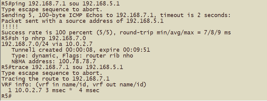
配置完成以上内容后,可以观察到的现象(例如:R5的192.168.5.0/24网段去往R7的192.168.7.0/24网段一跳可达)
IPSec加密
配置ISAKMP第一阶段策略
crypto isakmp policy 10
 encr 3des
 hash md5
 authentication pre-share
 group 2
配置ISAKMP预共享密码
crypto isakmp key Cisco@123 address 0.0.0.0
配置IPSec策略(转换集)
crypto ipsec transform-set DMVPN esp-3des esp-md5-hmac
 mode transport
配置IPSec profile
crypto ipsec profile DMVPN
 set transform-set DMVPN
调用IPSec profile
interface Tunnel0
 tunnel protection ipsec profile DMVPN
以上命令配置完成后,使用命令sh run | s crypto 查看配置,复制粘贴到其他设备上,然后在在tunnel接口调用
R1#sh run | s crypto
crypto isakmp policy 10
 encr 3des
 hash md5
 authentication pre-share
 group 2
crypto isakmp key Cisco@123 address 0.0.0.0
crypto ipsec transform-set DMVPN esp-3des esp-md5-hmac
 mode transport
crypto ipsec profile DMVPN
 set transform-set DMVPN
R1#
Hub1和Hub2接口调用时后边添加share可能遇到只有一个隧道起来的情况(不懂是模拟器bug还是怎么滴),按照思科官网配置两个不同名称的ipsec profile再次进行调用,可以解决
R2#sh run | s crypto
crypto isakmp policy 10
 encr 3des
 hash md5
 authentication pre-share
 group 2
crypto isakmp key Cisco@123 address 0.0.0.0
crypto ipsec transform-set DMVPN esp-3des esp-md5-hmac
 mode transport
crypto ipsec profile DMVPN-0
 set transform-set DMVPN
crypto ipsec profile DMVPN-1
 set transform-set DMVPN
R2#
验证加密
在R4上清空会话
R4#clea crypto session
R4#sh crypto engine connections active
Crypto Engine Connections

   ID  Type    Algorithm           Encrypt  Decrypt LastSeqN IP-Address
   45  IPsec   3DES+MD5                  0        2        2 100.48.48.4
   46  IPsec   3DES+MD5                  2        0        0 100.48.48.4
 1016  IKE     MD5+3DES                  0        0        0 100.48.48.4
使用ping命令产生数据
R4#ping 192.168.7.1 source 192.168.4.1 repeat 100
Type escape sequence to abort.
Sending 100, 100-byte ICMP Echos to 192.168.7.1, timeout is 2 seconds:
Packet sent with a source address of 192.168.4.1
!!!!!!!!!!!!!!!!!!!!!!!!!!!!!!!!!!!!!!!!!!!!!!!!!!!!!!!!!!!!!!!!!!!!!!
!!!!!!!!!!!!!!!!!!!!!!!!!!!!!!
Success rate is 100 percent (100/100), round-trip min/avg/max = 4/10/27 ms
查看加解密数据包计数
R4#sh crypto engine connections active
Crypto Engine Connections

   ID  Type    Algorithm           Encrypt  Decrypt LastSeqN IP-Address
   45  IPsec   3DES+MD5                  0       13       13 100.48.48.4
   46  IPsec   3DES+MD5                 13        0        0 100.48.48.4
   47  IPsec   3DES+MD5                  0        0        0 100.48.48.4
   48  IPsec   3DES+MD5                 92        0        0 100.48.48.4
   49  IPsec   3DES+MD5                  0       93       93 100.48.48.4
   50  IPsec   3DES+MD5                  0        0        0 100.48.48.4
 1016  IKE     MD5+3DES                  0        0        0 100.48.48.4
 1017  IKE     MD5+3DES                  0        0        0 100.48.48.4
 1018  IKE     MD5+3DES                  0        0        0 100.48.48.4

R4#
结果显示,加密或解密的数量分别超过100
NHRP工作流程
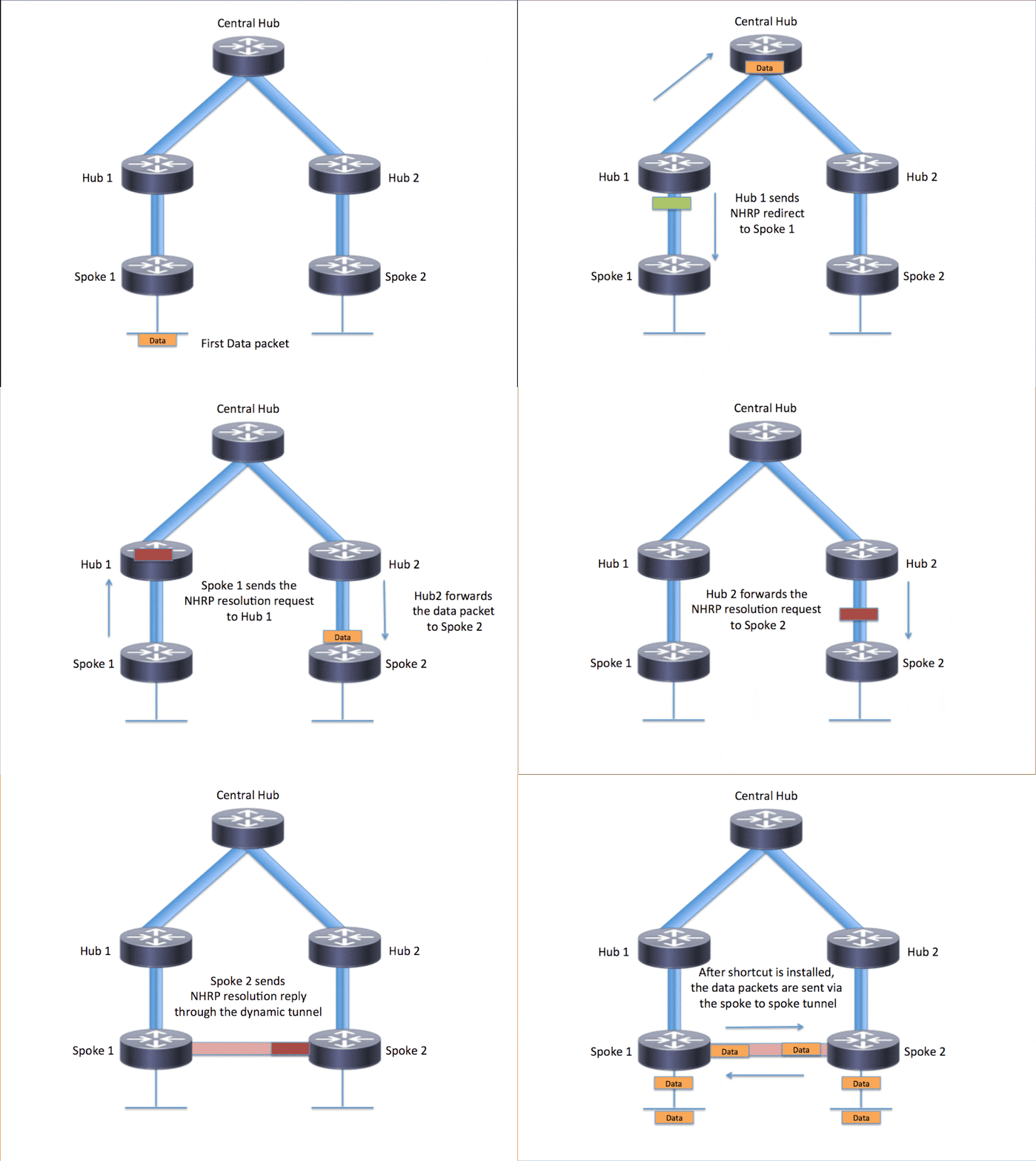
详细的可以去思科网站看看,这里贴个图
大致单向流程(以Spoke1(192.168.4.1)到Spoke4(192.168.7.1)为例):
- 当Spoke1首次与Spoke4进行通信(第一个数据包流,比如ping)或动态隧道已过期,icmp request 到达Hub1,查询nhrp缓存,发现没有192.168.7.1的缓存记录,icmp request 根据路由表和nhrp迭代转发到Hub1
- Hub1收到icmp request ,由于Hub1不是192.168.7.1的终点,于是向Spoke1发送nhrp 重定向(指示Spoke1发nhrp request),同时icmp request 根据路由表和nhrp迭代转发到Central Hub
- Central Hub收到icmp request,由于Central Hub不是192.168.7.1的终点,于是向Spoke1发送nhrp 重定向(往tunnel0发送,Hub1收到后再转发到tunnel1上,指示Spoke1发nhrp request,),同时icmp request 根据路由表和nhrp迭代转发到Hub2
- Hub2收到icmp request,由于Hub2不是192.168.7.1的终点,于是向Spoke1发送nhrp 重定向(往tunnel0发送,再转发到tunnel1,指示Spoke1发nhrp request),同时icmp request 根据路由表和nhrp迭代转发到Spoke4
- Spoke4收到icmp request,由于Spoke4是192.168.7.1的终点,在收到Spoke1的nhrp request于是向Spoke1发送Resolution Reply(沿着来的的路径逐条转发回去) ,icmp request 到达目的地
返回流程也是经过一轮重定向的操作,因为当icmp request 到达目的地后,Spoke4的nhrp缓存也没有192.168.4.1的条目或者说没有形成动态的tunnel
通过debug nhrp packet观察,nhrp的重定向、 request 消息在几十毫秒内全部完成
R2和R3之间也会发送重定向和request,因为运行了ospf协议,R2和R3之间有Spoke的路由(例如R2去往R6,R7的下一跳是R3的tunnel接口地址)
假设R2和R3直接已经形成动态隧道(R2ping通R3的tunnel0接口)那么Spoke1(192.168.4.1)到Spoke4(192.168.7.1)的首次通信跟踪路径如下
R4#tra 192.168.6.1 sou 192.168.4.1
Type escape sequence to abort.
Tracing the route to 192.168.6.1
VRF info: (vrf in name/id, vrf out name/id)
  1 10.0.1.2 9 msec 8 msec 8 msec
  2 10.0.0.3 11 msec 11 msec 15 msec
  3 10.0.2.6 19 msec *  14 msec
R4#

在路由器上使用命令清空nhrp缓存,再次使用trace可以看到数据包经过了R1
R1#clea ip nhrp
R2#clea ip nhrp
R3#clea ip nhrp
R4#clea ip nhrp
R6#clea ip nhrp

R4#tra 192.168.6.1 sou 192.168.4.1
Type escape sequence to abort.
Tracing the route to 192.168.6.1
VRF info: (vrf in name/id, vrf out name/id)
  1 10.0.1.2 11 msec 11 msec 9 msec
  2 10.0.0.1 11 msec 11 msec 17 msec
  3 10.0.0.3 19 msec 13 msec 12 msec
  4 10.0.2.6 18 msec *  14 msec
R4#
Spoke站点外网地址
Spoke站点是静态或动态的公网IP不影响
但是如果Spoke站点的出口地址是私网地址呢?不要惊奇,十几年前就发现有这种现象了,或者说Spoke站点上一级有NAT设备,这种情况下DMVPN仍然可用(前提是运营商没把UDP500给干掉)
在上面的拓扑R7和R8之间添加R9,配置NAT,R7和R9之间配置10.79.79.0网段,完成配置后发现R7学习路由和连通性测试没有问题,R3上观察nhrp缓存如下:
R3#sh ip nhrp
10.0.0.1/32 via 10.0.0.1
   Tunnel0 created 00:12:47, never expire
   Type: static, Flags: used
   NBMA address: 100.18.18.1
10.0.2.6/32 via 10.0.2.6
   Tunnel1 created 00:12:35, expire 00:09:08
   Type: dynamic, Flags: registered used nhop
   NBMA address: 100.68.68.6
10.0.2.7/32 via 10.0.2.7
   Tunnel1 created 00:00:25, expire 00:09:35
   Type: dynamic, Flags: registered used nhop
   NBMA address: 100.89.89.9
    (Claimed NBMA address: 10.79.79.7)

比正常的显示多了一行  (Claimed NBMA address: 10.79.79.7)
R9上查看NAT转换,是不是很熟悉哈,在IPSec VPN穿越NAT的时候也出现过这种情况,所以我想说DMVPN是IPSec VPN 的PLUS+PRO+MAX升级版
R9#sh ip nat translations
Pro Inside global      Inside local       Outside local      Outside global
udp 100.89.89.9:500    10.79.79.7:500     100.58.58.5:500    100.58.58.5:500
udp 100.89.89.9:500    10.79.79.7:500     200.38.38.3:500    200.38.38.3:500
udp 100.89.89.9:4500   10.79.79.7:4500    100.58.58.5:4500   100.58.58.5:4500
udp 100.89.89.9:4500   10.79.79.7:4500    200.38.38.3:4500   200.38.38.3:4500
R9#
经典结尾扯蛋
- 整了这么个实验,精华部分也就是nhrp的重定向和Spoke站点之间的动态隧道
- 在本人接触过的Hub和Spoke组网的项目中,也就接触过IPSec VPN,分支站点向中心传数据的情况,至于站点和站点互通的少见
- 其实使用DMVPN组网也能完成分支站点仅向中心传数据;在实际的项目中怀疑是参杂了一些利益因素导致这种组网少见,可能是我见识短浅;因为这种技术也不会向友商设备提供对接,跟你对接了我岂不是少赚钱了
- 而IPSec VPN则不同,它是一个安全框架,遵守框架开发理论上都能对接,本人提到的第二点的项目中对接的设备有深信服,华三,华为,迈普,绿盟,都组网正常运行了
- 做完这个实验去瞄了一眼华为的DSVPN,配置项差不多,命令表现形式不一样
- 配置存阿里云盘了,这是链接:[分享的文件 ]
- 欢迎“
来电”来函探讨。
