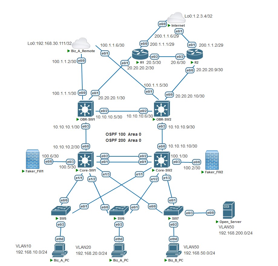
红茶三杯的原文 :【有点儿意思系列 04】哎哟喂停不下来了 ,根据问题延续中的表述, 实验拓扑增加了两台出口路由器,两台防火墙,一台服务器。本次拓扑实验依托上一个拓扑演变而来,大部分基础配置与上一个相同,如果您是初次看到本文,请参阅上文 【No.002 Simple Case 】,本文不在赘述。
可能你看到拓扑中防火墙名称就懵了,我解释一下,由于我这是台古董级 AMD CPU 的电脑,跑不起 Cisco ASAv 的镜像(报错:Unsupport CPU type,无限重启),再加上内存有限,就不折腾了,考虑到文中只提到 NAT 的需求,我就用两台路由器换个图标和名称代替了。最终实现了原文中源地址转换及静态映射的需求,虽然牺牲了安全策略配置和 HA 配置。
极致极简,拓扑中的 Open_Server 同样是用路由器模拟的,实验中将实现 Open_Server 的 SSH 服务映射到公网地址提供访问。
Part 1
Step 1:修改 Core-SW1 和 Core-SW2 配置
! --- Core-SW1 配置,增加与 Faker_FW1 互联地址,OSPF 宣告互联地址
!
interface Ethernet0/3
 no switchport
 ip vrf forwarding vpn_internet
 ip address 192.168.100.5 255.255.255.252
!
router ospf 200 vrf vpn_internet
 network 192.168.100.5 0.0.0.0 area 0
!
! --- Core-SW2 配置,增加与 Faker_FW2 互联地址,OSPF 宣告互联地址
!
interface Ethernet0/3
 no switchport
 ip vrf forwarding vpn_internet
 ip address 192.168.100.1 255.255.255.252
!
router ospf 200 vrf vpn_internet
 network 192.168.100.1 0.0.0.0 area 0
!
Step 2:修改 OBR-SW1 和 OBR-SW2 配置
! --- OBR-SW1 配置,配置与 R1 互联地址,OSPF 宣告互联地址,去除原先的 NAT 相关配置和去除 OSPF 注入默认路由
!
interface Ethernet0/1
 no switchport
 ip vrf forwarding vpn_internet
 ip address 20.20.20.1 255.255.255.252
 ip ospf network point-to-point
!
router ospf 200 vrf vpn_internet
 network 20.20.20.1 0.0.0.0 area 0
!
! --- OBR-SW2 配置,配置与 R2 互联地址,OSPF 宣告互联地址,去除原先的 NAT 相关配置和去除 OSPF 注入默认路由
!
interface Ethernet0/0
 no switchport
 ip vrf forwarding vpn_internet
 ip address 20.20.20.10 255.255.255.252
 ip ospf network point-to-point
!
router ospf 200 vrf vpn_internet
 network 20.20.20.10 0.0.0.0 area 0
!
Step 3:配置 R1 和 R2
! --- R1 配置,配置互联地址,OSPF 宣告互联地址
! --- 配置中包含了 NAT 配置,当两台防火墙宕机后仍可保持内网与互联网通信
!
ip vrf vpn_internet
 rd 20:20
 route-target export 200:200
 route-target import 200:200
!
interface Ethernet0/0
 ip vrf forwarding vpn_internet
 ip address 200.1.1.1 255.255.255.248
 ip nat outside
 ip virtual-reassembly in
 duplex auto
!
interface Ethernet0/1
 ip vrf forwarding vpn_internet
 ip address 20.20.20.2 255.255.255.252
 ip nat inside
 ip virtual-reassembly in
 ip ospf network point-to-point
 duplex auto
!
interface Ethernet0/2
 ip vrf forwarding vpn_internet
 ip address 20.20.20.5 255.255.255.252
 ip nat inside
 ip virtual-reassembly in
 ip ospf network point-to-point
 duplex auto
!
router ospf 200 vrf vpn_internet
 router-id 111.111.111.111
 network 20.20.20.2 0.0.0.0 area 0
 network 20.20.20.5 0.0.0.0 area 0
 network 200.1.1.1 0.0.0.0 area 0
 default-information originate metric 11 metric-type 1
!
ip nat inside source list 10 interface Ethernet0/0 vrf vpn_internet overload
!
ip route vrf vpn_internet 0.0.0.0 0.0.0.0 200.1.1.6
!
access-list 10 permit 192.168.50.0 0.0.0.255
!
! --- R2 配置,配置互联地址,OSPF 宣告互联地址
! --- 配置中包含了 NAT 配置,当两台防火墙宕机后仍可保持内网与互联网通信
!
interface Ethernet0/0
 ip vrf forwarding vpn_internet
 ip address 20.20.20.9 255.255.255.252
 ip nat inside
 ip virtual-reassembly in
 ip ospf network point-to-point
 duplex auto
!
interface Ethernet0/1
 ip vrf forwarding vpn_internet
 ip address 200.1.1.2 255.255.255.248
 ip nat outside
 ip virtual-reassembly in
 duplex auto
!
interface Ethernet0/2
 ip vrf forwarding vpn_internet
 ip address 20.20.20.6 255.255.255.252
 ip nat inside
 ip virtual-reassembly in
 ip ospf network point-to-point
 duplex auto
!
router ospf 200 vrf vpn_internet
 router-id 222.222.222.222
 network 20.20.20.6 0.0.0.0 area 0
 network 20.20.20.9 0.0.0.0 area 0
 network 200.1.1.2 0.0.0.0 area 0
 default-information originate metric 10 metric-type 1
!
ip nat inside source list 10 interface Ethernet0/1 vrf vpn_internet overload
!
ip route vrf vpn_internet 0.0.0.0 0.0.0.0 200.1.1.6
!
access-list 10 permit 192.168.50.0 0.0.0.255
!
Step 4:Internet 配置,Faker_FW1、Faker_FW2 基础配置
! --- Internet 配置
!
interface Loopback0
 ip address 1.2.3.4 255.255.255.255
!
interface Ethernet0/0
 switchport access vlan 123
!
interface Vlan123
 ip address 200.1.1.6 255.255.255.248
!
! --- Faker_FW1 配置
! --- 200.1.1.3 是 NAT 和 映射使用的公网地址
!
interface Loopback0
 ip address 200.1.1.3 255.255.255.255
!
interface Ethernet0/0
 ip address 192.168.100.6 255.255.255.252
!
! --- Faker_FW2 配置
! --- 200.1.1.4 是 NAT 和 映射使用的公网地址
!
interface Loopback0
 ip address 200.1.1.4 255.255.255.255
!
interface Ethernet0/0
 ip address 192.168.100.2 255.255.255.252
!
Part 2
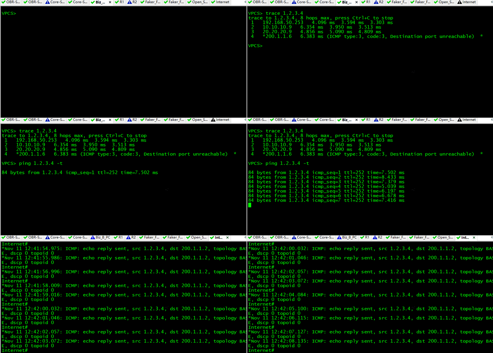
- 配置完第一部分, Biz_B_PC 可以 ping 通 Internet 的 1.2.3.4,路径是: Core-SW2 -> OBR-SW2 -> R2,而从 Internet 开启 debug ip icmp 观察到:Internet 返回 reply 报文远端地址是 R2 的外网接口 IP 地址(200.1.1.2)。
根据原文中的描述,“ 防火墙与核心交换机为仅有一条物理线路。另外,由于增加了防火墙,因此将原先部署在出口路由器(拓扑中没有画出来)上的NAT下沉到防火墙上,由防火墙来部署源地址转换及静态映射。防火墙出公网的下一跳是OBR-SW交换机,两者使用私有IP地址三层对接。”
也就是 NAT 和映射的功能交给了防火墙设备,然后防火墙出公网的下一跳是出口设备,联想到防火墙与出口路由器之间创建一条隧道,内网去往公网的 inside source IP 地址在防火墙上进行 NAT 后直接走隧道至出口路由器,再路由出去。我在两台防火墙上配置的环回接口地址就是转换用的。
Step 1:配置 Faker_FW 与出口路由器建立 GRE 隧道
! --- Faker_FW2 配置
! --- NAT 和 映射使用的公网地址
interface Loopback0
 ip address 200.1.1.4 255.255.255.255
! --- 使用 e0/0 接口地址与 R2 的 e0/0 接口地址建立隧道,并配置 nat outside
interface Tunnel0
 ip address 1.1.1.2 255.255.255.252
 ip nat outside
 ip virtual-reassembly in
 tunnel source 192.168.100.2
 tunnel destination 20.20.20.9
! --- 配置 nat inside
interface Ethernet0/0
 ip nat inside
! --- 配置 NAT overload 和 静态映射(将内网 Open_Server 的 SSH 端口映射到公网的 2222 端口)
ip nat pool nat-pat 200.1.1.4 200.1.1.4 prefix-length 29
ip nat inside source list 10 pool nat-pat overload
ip nat inside source static tcp 192.168.50.200 22 200.1.1.4 2222 extendable
! --- 配置默认路由和必要的静态路由
ip route 0.0.0.0 0.0.0.0 Tunnel0
ip route 20.20.20.8 255.255.255.252 192.168.100.1
ip route 192.168.50.0 255.255.255.0 192.168.100.1
! --- 配置 inside source list
access-list 10 permit 192.168.50.0 0.0.0.255
!
! --- R2 配置
! --- 使用 e0/0 接口地址与 Faker_FW2 的 e0/0 接口地址建立隧道
interface Tunnel0
 ip vrf forwarding vpn_internet
 ip address 1.1.1.1 255.255.255.252
 tunnel source 20.20.20.9
 tunnel destination 192.168.100.2
 tunnel vrf vpn_internet
! --- 配置需要走隧道的 VRF 静态路由,内网地址回程路由 track 跟踪
ip route vrf vpn_internet 192.168.50.0 255.255.255.0 Tunnel0 track 1
ip route vrf vpn_internet 200.1.1.4 255.255.255.255 Tunnel0
! --- 配置 SLA 监测隧道对端的连通性
ip sla 1
 icmp-echo 192.168.100.2 source-interface Ethernet0/0
 vrf vpn_internet
ip sla schedule 1 life forever start-time now
!
track 1 ip sla 1 reachability
!
! --- Faker_FW1 配置
! --- NAT 和 映射使用的公网地址
interface Loopback0
 ip address 200.1.1.3 255.255.255.255
! --- 使用 e0/0 接口地址与 R1 的 e0/1 接口地址建立隧道,并配置 nat outside
interface Tunnel0
 ip address 2.2.2.1 255.255.255.252
 ip nat outside
 ip virtual-reassembly in
 tunnel source 192.168.100.6
 tunnel destination 20.20.20.2
! --- 配置 nat inside
interface Ethernet0/0
 ip nat inside
! --- 配置 NAT overload 和 静态映射
ip nat pool nat-pat 200.1.1.3 200.1.1.3 prefix-length 29
ip nat inside source list 10 pool nat-pat overload
ip nat inside source static tcp 192.168.50.200 22 200.1.1.3 2222 extendable
! --- 配置默认路由和必要的静态路由
ip route 0.0.0.0 0.0.0.0 Tunnel0
ip route 20.20.20.0 255.255.255.252 192.168.100.5
ip route 192.168.50.0 255.255.255.0 192.168.100.5
!
! --- 配置 inside source list
access-list 10 permit 192.168.50.0 0.0.0.255
!
! --- R1 配置
! --- 使用 e0/1 接口地址与 Faker_FW2 的 e0/0 接口地址建立隧道
interface Tunnel0
 ip vrf forwarding vpn_internet
 ip address 2.2.2.2 255.255.255.252
 tunnel source 20.20.20.2
 tunnel destination 192.168.100.6
 tunnel vrf vpn_internet
! --- 配置需要走隧道的 VRF 静态路由,内网地址回程路由 track 跟踪
ip route vrf vpn_internet 192.168.50.0 255.255.255.0 Tunnel0 track 1
ip route vrf vpn_internet 200.1.1.3 255.255.255.255 Tunnel0
! --- 配置 SLA 监测隧道对端的连通性
ip sla 1
 icmp-echo 192.168.100.6 source-interface Ethernet0/1
 vrf vpn_internet
ip sla schedule 1 life forever start-time now
!
track 1 ip sla 1 reachability
!
Step 2:配置 Core-SW 静态路由使上网流量下一跳设备为防火墙
! --- Core-SW1 配置
!
ip route vrf vpn_internet 0.0.0.0 0.0.0.0 192.168.100.6 track 1
!
ip sla 1
 icmp-echo 192.168.100.6 source-interface Ethernet0/3
 vrf vpn_internet
 frequency 5
!
track 1 ip sla 1 reachability
!
! --- Core-SW2 配置
!
ip route vrf vpn_internet 0.0.0.0 0.0.0.0 192.168.100.2 track 1
!
ip sla 1
 icmp-echo 192.168.100.2 source-interface Ethernet0/3
 vrf vpn_internet
 frequency 5
!
track 1 ip sla 1 reachability
!
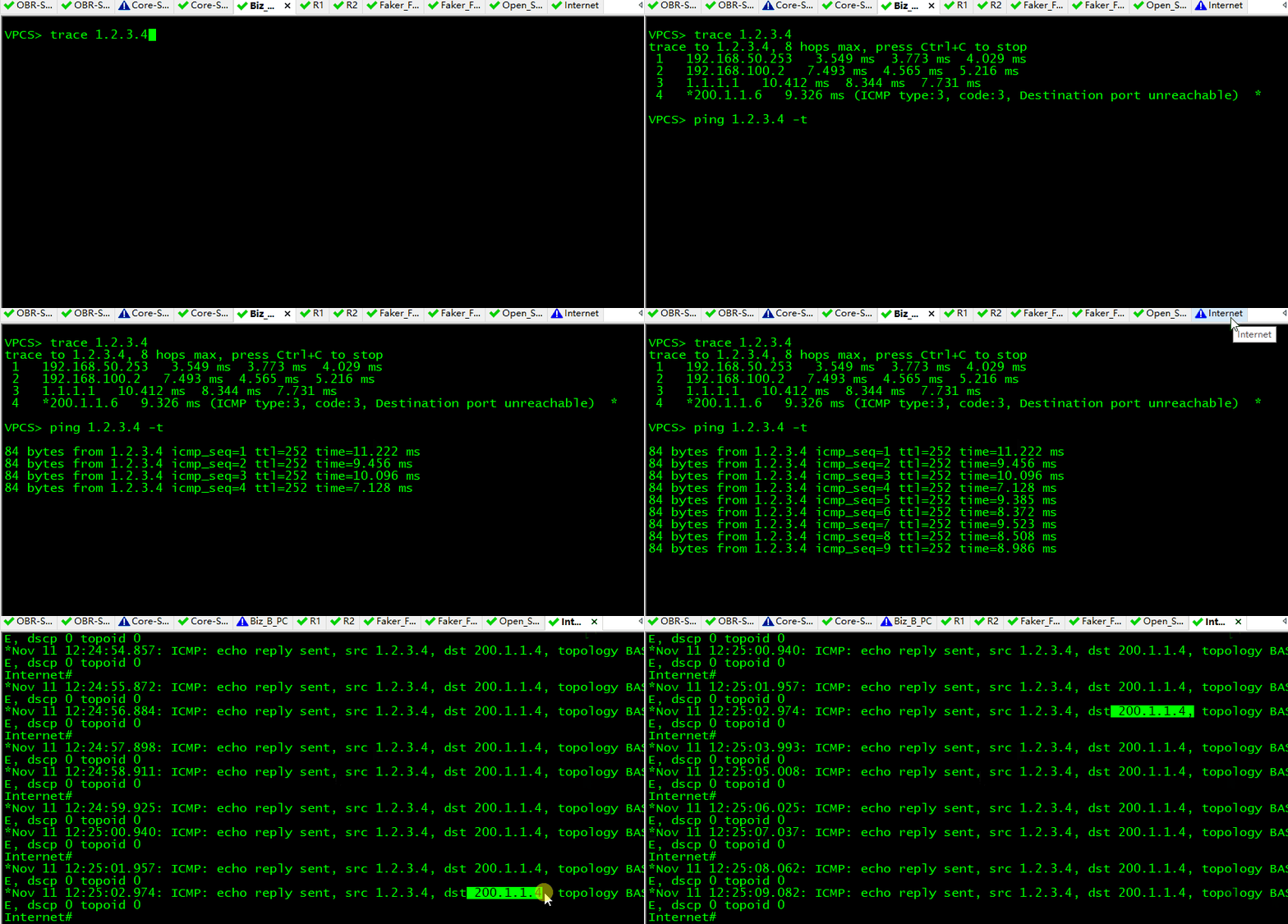
完成配置到这个步骤,再观察内网到 Internet 的流量路径,: Core-SW2 -> Faker_FW2 -> R2,而从 Internet 开启 debug ip icmp 观察到:Internet 返回的 reply 报文远端地址是 Faker_FW2 配置的 NAT 转换地址(200.1.1.4)。
配置 Open_Server 和测试公网 SSH 访问
! --- Open_Server 配置
!
interface Ethernet0/0
 ip address 192.168.50.200 255.255.255.0
!
ip route 0.0.0.0 0.0.0.0 192.168.50.254
!
! --- 配置 SSH SERVICES
!
ip domain name test.com
!
crypto key generate rsa
1024
!
ip ssh version 2
!
line vty 0 4
 login local
 transport input ssh
!
username cisco password 0 cisco
!
enable password cisco
!
NAT 静态映射已在 【Part 2 – Step 1】 中配置,将 Open_Server 的 22 端口映射到被访问公网 IP 地址的 2222 端口。测试结果如图:
Part 3
网络冗余的设计
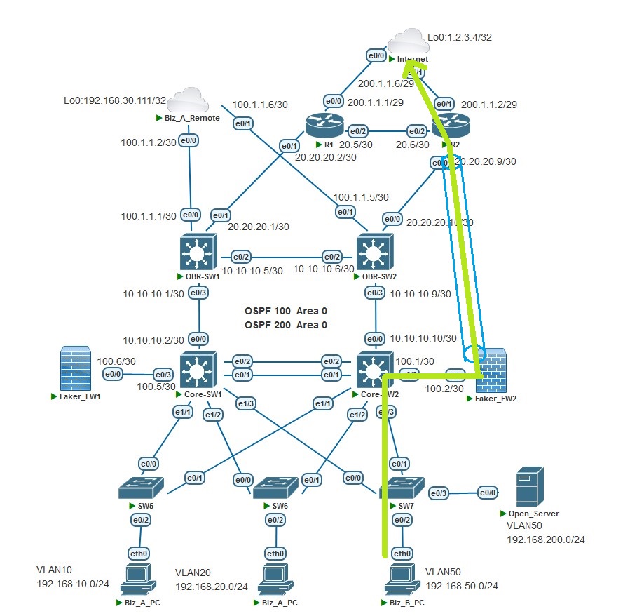
本实验中探讨的是在网络中某段线路通断的情况下 Biz_B_PC 访问 Internet 环回接口地址 1.2.3.4 的路径切换。网络正常情况下,访问路径如下图:
情况 1:(假设 Faker_FW1、Core-SW1、OBR-SW1、R1 设备都正常,线路也正常 )
当 Core-SW2 的 e0/3 状态为 DOWN;
当 Core-SW2 的 e0/0 状态为 DOWN;
当 OBR-SW2 的 e0/0 状态为 DOWN;
当 Core-SW2 的 e1/3 链路协议 DOWN;
以上四个条件有一个为真,即其中出现一个接口为 DOWN 状态, Core-SW2 降低 内网 VRRP 组的优先级, 同时将内网 VRRP 组切换至 Backup 状态,内网上网流量路径切换至 Core-SW1 进行转发。
情况 2:(假设 Faker_FW2、 Core-SW2、OBR-SW2、R2 设备都正常,线路也正常 )
当 Core-SW1 的 e0/3 状态为 DOWN;
当 Core-SW1 的 e0/0 状态为 DOWN;
当 OBR-SW1 的 e0/1 状态为 DOWN;
当 Core-SW1 的 e1/3 链路协议 DOWN;
以上四个条件有一个为真,即其中出现一个接口为 DOWN 状态, Core-SW1 降低 内网 VRRP 组的优先级,不进行 VRRP 状态切换。
情况 3:
当 A 组条件任一条件为真和 B 组任一条件为真时,此时 Core-SW1 和 Core-SW2 都降低 VRRP 组优先级,由于设置了 Core-SW2 的 VRRP 优先级为 120 ( Core-SW1 默认优先级 100),两台设备同时降低相同的优先级 21 。此时的 VRRP Master 设备是 Core-SW2 ,上网流量路径:Core-SW2 -> OBR-SW2 -> R2 ,在 R2 上进行 NAT 最终出公网;当 B 组中的条件是:OBR-SW2 的 e0/0 状态为 DOWN,上网流量路径:Core-SW2 -> OBR-SW2 -> OBR-SW1-> R1,在 R1 上进行 NAT 最终出公网。
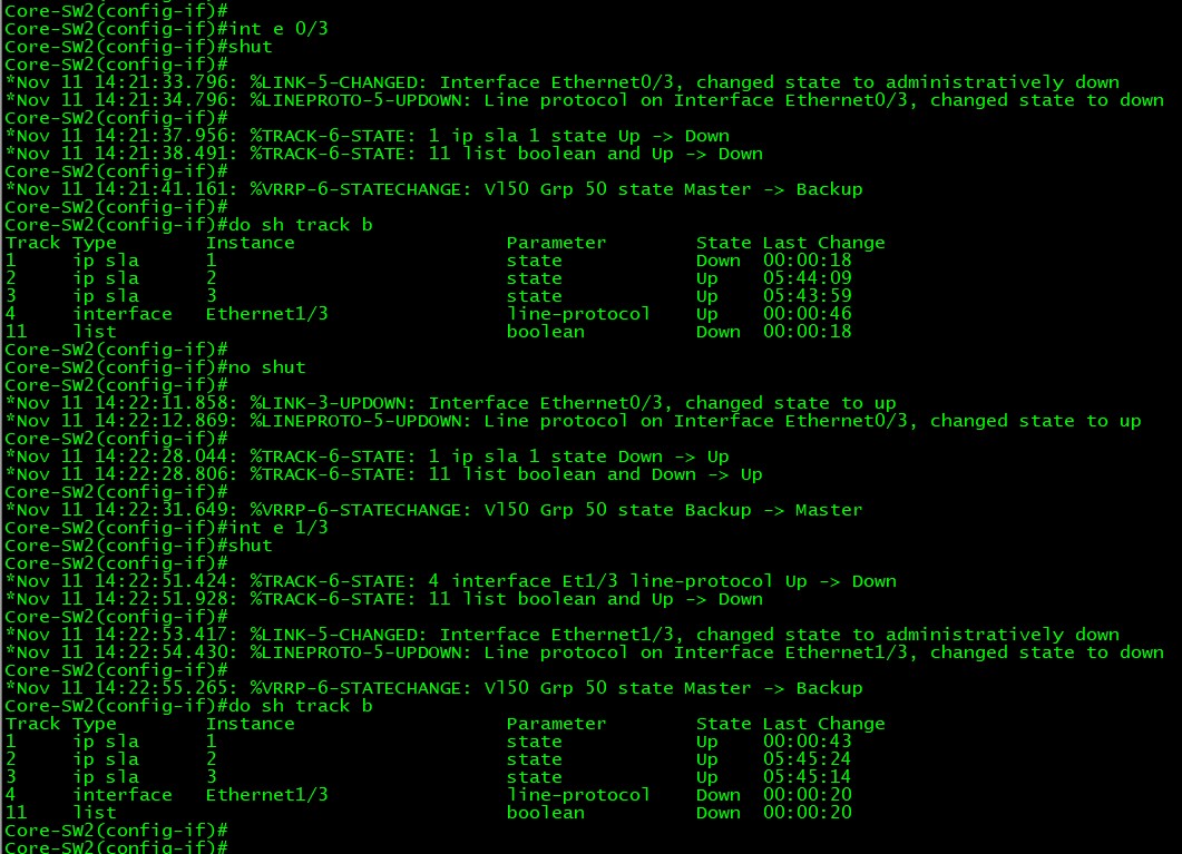
分别手动 shutdown 以上任一条件中的接口(以 Core-SW2 的 e0/3 和 e1/3 为例),观察 Track 和 VRRP 状态的变化如下图:
! --- Core-SW2 配置
!
ip sla 1
 icmp-echo 192.168.100.2 source-interface Ethernet0/3
 vrf vpn_internet
 frequency 5
ip sla 2
 icmp-echo 10.10.10.9 source-interface Ethernet0/0.200
 vrf vpn_internet
 frequency 5
ip sla 3
 icmp-echo 20.20.20.10 source-interface Ethernet0/0.200
 vrf vpn_internet
 frequency 5
ip sla group schedule 11 1-3 schedule-together start-time now life forever
!
track 1 ip sla 1
!
track 2 ip sla 2
!
track 3 ip sla 3
!
track 4 interface Ethernet1/3 line-protocol
!
track 11 list boolean and
 object 1
 object 2
 object 3
 object 4
!
interface Vlan50
 vrrp 50 priority 120
 vrrp 50 track 11 decrement 21
!
! --- Core-SW1 配置
!
ip sla 1
 icmp-echo 192.168.100.6 source-interface Ethernet0/3
 vrf vpn_internet
 frequency 5
ip sla 2
 icmp-echo 10.10.10.1 source-interface Ethernet0/0.200
 vrf vpn_internet
 frequency 5
ip sla 3
 icmp-echo 20.20.20.1 source-interface Ethernet0/0.200
 vrf vpn_internet
 frequency 5
ip sla group schedule 11 1-3 schedule-together start-time now life forever
!
track 1 ip sla 1 reachability
!
track 2 ip sla 2 reachability
!
track 3 ip sla 3 reachability
!
track 4 interface Ethernet1/3 line-protocol
!
track 11 list boolean and
 object 1
 object 2
 object 3
 object 4
!
interface Vlan50
 vrrp 50 ip 192.168.50.254
 vrrp 50 track 11 decrement 21
!
Ending
- 码完字了,还是那句话(挺耗时间的)。尽管还有不满意的地方,比如还可以再完善配置,添加更多的配置参数,考虑更多扩展需求想解决思路,但是这是个“无底洞”。
- 文中可能有些配置未提及或内容术语表述的不规范,请见谅。
- 配置存阿里云盘了,这是链接:[分享的文件 ]
- 欢迎“
来电”来函探讨。
