来自红茶三杯的原文:【有点儿意思系列 04】哎哟喂停不下来了
当时看完 Case 的需求我是不想理会的,不就是 VRF 隔离么,我压根没往配置 ACL 这个方向去,其实看需求已经暗示的非常明显了,“始终”,“完全隔离” 等等字眼。再加上 VRRP(远离思科设备多年,不玩 HSRP 了,模拟器做不了堆叠啊) 的冗余方案。但是 “问题后续” 这段话引起了我的兴趣,还是从这个拓扑开始吧(其实我已经做完两个拓扑在码这篇文章的时候),话不多说,开干。
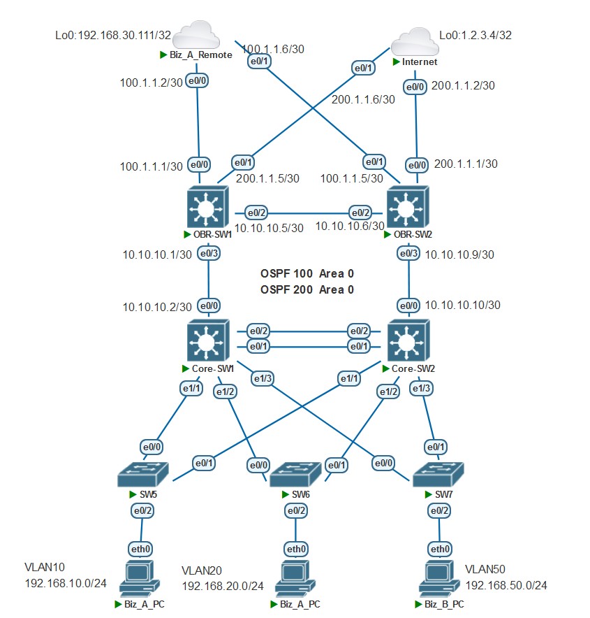
Step 1:配置接入层交换机(SW5、SW6、SW7)
创建 VLAN ,上联 Core-SW 的端口配置 Trunk 放行 VLAN,把连接 PC 的端口划入对应 VLAN
! -- SW5 配置, 根据需求业务 A 有多个 VLAN ,就敷衍一下配置VLAN10,VLAN20
!
vlan 10
vlan 20
!
interface Ethernet0/0
 switchport trunk allowed vlan 10,20
 switchport trunk encapsulation dot1q
 switchport mode trunk
!
interface Ethernet0/1
 switchport trunk allowed vlan 10,20
 switchport trunk encapsulation dot1q
 switchport mode trunk
!
interface Ethernet0/2
 switchport access vlan 10
!
SW6、SW7 如法炮制即可。
Step 2:配置 Core_SW1 和 Core_SW2
创建 VLAN10、VLAN20、VLAN50,创建 VRF 定义为 vpn_biz 和 vpn_internet
! --- Core_SW1 和 Core_SW2 配置
!
vlan 10
vlan 20
vlan 50
!
! --- 其实用不到 RD 和 RT ,在 MPLS-VPN 引入的时候才用,为了看起来好看点
ip vrf vpn_biz
 rd 10:10
 route-target export 100:100
 route-target import 100:100
!
ip vrf vpn_internet
 rd 20:20
 route-target export 200:200
 route-target import 200:200
!
配置 Core-SW1 与 Core-SW2 之间的 Port-channel,配置 Core-SW 和下联 SW5、SW6、SW7 的 Trunk
! --- Core_SW1 和 Core_SW2 配置
!
interface Port-channel1
 switchport trunk allowed vlan 10,20,50
 switchport trunk encapsulation dot1q
 switchport mode trunk
!
interface Ethernet0/1
 switchport trunk allowed vlan 10,20,50
 switchport trunk encapsulation dot1q
 switchport mode trunk
 channel-group 1 mode active
!
interface Ethernet0/2
 switchport trunk allowed vlan 10,20,50
 switchport trunk encapsulation dot1q
 switchport mode trunk
 channel-group 1 mode active
!
interface Ethernet1/1
 switchport trunk allowed vlan 10,20
 switchport trunk encapsulation dot1q
 switchport mode trunk
!
interface Ethernet1/2
 switchport trunk allowed vlan 10,20
 switchport trunk encapsulation dot1q
 switchport mode trunk
!
interface Ethernet1/3
 switchport trunk allowed vlan 50
 switchport trunk encapsulation dot1q
 switchport mode trunk
!
创建 VLAN 接口并绑定 VRF,配置 IP 地址,配置 VRRP
! --- Core_SW1 配置
!
interface Vlan10
 ip vrf forwarding vpn_biz
 ip address 192.168.10.252 255.255.255.0
 vrrp 10 ip 192.168.10.254
 vrrp 10 priority 120
!
interface Vlan20
 ip vrf forwarding vpn_biz
 ip address 192.168.20.252 255.255.255.0
 vrrp 20 ip 192.168.20.254
 vrrp 20 priority 120
!
interface Vlan50
 ip vrf forwarding vpn_internet
 ip address 192.168.50.252 255.255.255.0
 vrrp 50 ip 192.168.50.254
!
! --- Core_SW2 配置 ! interface Vlan10 ip vrf forwarding vpn_biz ip address 192.168.10.253 255.255.255.0 vrrp 10 ip 192.168.10.254 ! interface Vlan20 ip vrf forwarding vpn_biz ip address 192.168.20.253 255.255.255.0 vrrp 20 ip 192.168.20.254 ! interface Vlan50 ip vrf forwarding vpn_internet ip address 192.168.50.253 255.255.255.0 vrrp 50 ip 192.168.50.254 vrrp 50 priority 120 !配置 Core-SW1 与 OBR-SW1 ,Core-SW2 与 OBR-SW2 互联的接口 IP 地址,并配置 OSPF 网络类型为点对点
! --- Core_SW1 配置
!
interface Ethernet0/0.100
 encapsulation dot1Q 100
 ip vrf forwarding vpn_biz
 ip address 10.10.10.2 255.255.255.252
 ip ospf network point-to-point
!
interface Ethernet0/0.200
 encapsulation dot1Q 200
 ip vrf forwarding vpn_internet
 ip address 10.10.10.2 255.255.255.252
 ip ospf network point-to-point
!
! --- Core_SW2 配置 ! interface Ethernet0/0.100 encapsulation dot1Q 100 ip vrf forwarding vpn_biz ip address 10.10.10.10 255.255.255.252 ip ospf network point-to-point ! interface Ethernet0/0.200 encapsulation dot1Q 200 ip vrf forwarding vpn_internet ip address 10.10.10.10 255.255.255.252 ip ospf network point-to-point !
Step 3:配置 OBR-SW1 和 OBR-SW2
配置创建 VRF 定义为 vpn_biz 和 vpn_internet,配置互联接口 IP 地址
! --- OBR-SW1 配置
!
ip vrf vpn_biz
 rd 10:10
 route-target export 100:100
 route-target import 100:100
!
ip vrf vpn_internet
 rd 20:20
 route-target export 200:200
 route-target import 200:200
!
!
interface Ethernet0/0
 no switchport
 ip vrf forwarding vpn_biz
 ip address 100.1.1.1 255.255.255.252
 ip ospf network point-to-point
!
interface Ethernet0/1
 no switchport
 ip vrf forwarding vpn_internet
 ip address 200.1.1.5 255.255.255.252
!
interface Ethernet0/2.100
 encapsulation dot1Q 100
 ip vrf forwarding vpn_biz
 ip address 10.10.10.5 255.255.255.252
 ip ospf network point-to-point
!
interface Ethernet0/2.200
 encapsulation dot1Q 200
 ip vrf forwarding vpn_internet
 ip address 10.10.10.5 255.255.255.252
 ip ospf network point-to-point
!
interface Ethernet0/3.100
 encapsulation dot1Q 100
 ip vrf forwarding vpn_biz
 ip address 10.10.10.1 255.255.255.252
 ip ospf network point-to-point
!
interface Ethernet0/3.200
 encapsulation dot1Q 200
 ip vrf forwarding vpn_internet
 ip address 10.10.10.1 255.255.255.252
 ip ospf network point-to-point
!
! --- OBR-SW2 配置 ! ip vrf vpn_biz rd 10:10 route-target export 100:100 route-target import 100:100 ! ip vrf vpn_internet rd 20:20 route-target export 200:200 route-target import 200:200 ! ! interface Ethernet0/0 no switchport ip vrf forwarding vpn_internet ip address 200.1.1.1 255.255.255.252 ! interface Ethernet0/1 no switchport ip vrf forwarding vpn_biz ip address 100.1.1.5 255.255.255.252 ip ospf network point-to-point ! interface Ethernet0/2.100 encapsulation dot1Q 100 ip vrf forwarding vpn_biz ip address 10.10.10.6 255.255.255.252 ip ospf network point-to-point ! interface Ethernet0/2.200 encapsulation dot1Q 200 ip vrf forwarding vpn_internet ip address 10.10.10.6 255.255.255.252 ip ospf network point-to-point ! interface Ethernet0/3.100 encapsulation dot1Q 100 ip vrf forwarding vpn_biz ip address 10.10.10.9 255.255.255.252 ip ospf network point-to-point ! interface Ethernet0/3.200 encapsulation dot1Q 200 ip vrf forwarding vpn_internet ip address 10.10.10.9 255.255.255.252 ip ospf network point-to-point !
Step 4:配置 Biz_A_Remote
配置创建 VRF 定义为 vpn_biz,配置互联接口 IP 地址,配置环回接口作为测试地址
! --- Biz_A_Remote 配置
!
ip vrf vpn_biz
 rd 10:10
 route-target export 100:100
 route-target import 100:100
!
!
interface Loopback0
 ip vrf forwarding vpn_biz
 ip address 192.168.30.111 255.255.255.255
 ip ospf network point-to-point
!
interface Ethernet0/0
 no switchport
 ip vrf forwarding vpn_biz
 ip address 100.1.1.2 255.255.255.252
 ip ospf network point-to-point
!
interface Ethernet0/1
 no switchport
 ip vrf forwarding vpn_biz
 ip address 100.1.1.6 255.255.255.252
 ip ospf network point-to-point
!
Step 5:配置 Internet
配置接口 IP 地址和环回接口即可,现实环境中,运营商的设备控制不了
! --- Internet 配置
!
interface Loopback0
 ip address 1.2.3.4 255.255.255.255
!
interface Ethernet0/0
 ip address 200.1.1.2 255.255.255.252
 duplex auto
!
interface Ethernet0/1
 ip address 200.1.1.6 255.255.255.252
 duplex auto
!
Step 6:配置 OSPF
为了简化配置过程,我全网使用 Area 0 ,生产环境中该划分区域的不要偷懒。
! --- Core_SW1 配置
!
router ospf 100 vrf vpn_biz
 router-id 1.1.1.1
 network 10.10.10.2 0.0.0.0 area 0
 network 192.168.10.252 0.0.0.0 area 0
 network 192.168.20.252 0.0.0.0 area 0
!
router ospf 200 vrf vpn_internet
 router-id 1.1.1.2
 network 10.10.10.2 0.0.0.0 area 0
 network 192.168.50.252 0.0.0.0 area 0
!
! --- Core_SW2 配置 ! router ospf 100 vrf vpn_biz router-id 2.2.2.1 network 10.10.10.10 0.0.0.0 area 0 network 192.168.10.253 0.0.0.0 area 0 network 192.168.20.253 0.0.0.0 area 0 ! router ospf 200 vrf vpn_internet router-id 2.2.2.2 network 10.10.10.10 0.0.0.0 area 0 network 192.168.50.253 0.0.0.0 area 0 !! --- OBR-SW1 配置 ! router ospf 100 vrf vpn_biz router-id 11.11.11.1 network 10.10.10.1 0.0.0.0 area 0 network 10.10.10.5 0.0.0.0 area 0 network 100.1.1.1 0.0.0.0 area 0 ! router ospf 200 vrf vpn_internet router-id 11.11.11.2 network 10.10.10.1 0.0.0.0 area 0 network 10.10.10.5 0.0.0.0 area 0 default-information originate always ! ip route vrf vpn_internet 0.0.0.0 0.0.0.0 200.1.1.6 !! --- OBR-SW2 配置 ! router ospf 100 vrf vpn_biz router-id 22.22.22.1 network 10.10.10.6 0.0.0.0 area 0 network 10.10.10.9 0.0.0.0 area 0 network 100.1.1.5 0.0.0.0 area 0 ! router ospf 200 vrf vpn_internet router-id 22.22.22.2 network 10.10.10.6 0.0.0.0 area 0 network 10.10.10.9 0.0.0.0 area 0 default-information originate always ! ip route vrf vpn_internet 0.0.0.0 0.0.0.0 200.1.1.2 !! --- Biz_A_Remote 配置 ! router ospf 100 vrf vpn_biz router-id 3.3.3.1 network 100.1.1.2 0.0.0.0 area 0 network 100.1.1.6 0.0.0.0 area 0 network 192.168.30.111 0.0.0.0 area 0 !
Step 7:配置 NAT
其实在生产环境中用核心交换机作为互联网出口的情况不常见(我没见过),核心交换机的上行可能会有行为管理器、安全设备、路由器等设备,具体情况就要看客户单位对网络有什么样的需求和预算了。
到这还有个问题,思科 CEF 和 NAT 貌似有冲突,去思科论坛看巴拉巴拉一大通大概是软件版本和硬件和处理器的类型等等问题,我这个是虚拟环境,不好判断是什么原因,放出看过的链接。各位如果知道是什么原因的请知会我,万分感谢。
对于上述问题,经过试验可行的方法是在需要配置 NAT 参数的接口关闭路由高速缓存
! --- OBR-SW1 配置
!
interface Ethernet0/1
 ip nat outside
 no ip route-cache
!
interface Ethernet0/2.200
 ip nat inside
 no ip route-cache
!
interface Ethernet0/3.200
 ip nat inside
 no ip route-cache
!
access-list 10 permit 192.168.50.0 0.0.0.255
!
ip nat inside source list 10 interface Ethernet0/1 overload
!
! --- OBR-SW2 配置 ! interface Ethernet0/0 ip nat outside no ip route-cache ! interface Ethernet0/2.200 ip nat inside no ip route-cache ! interface Ethernet0/3.200 ip nat inside no ip route-cache ! access-list 10 permit 192.168.50.0 0.0.0.255 ! ip nat inside source list 10 interface Ethernet0/0 overload !
Step 8:Test
- Biz_A_PC 和 Biz_B_PC 测试,发现两个网络之间不能互通。Biz_A_PC 能 ping 通 Biz_A_Remote 的环回地址 192.168.30.111;Biz_B_PC 能 ping 通 Internet 的环回地址 1.2.3.4

冗余测试
由于这个拓扑实验和我写的下一篇文章有大量重叠部分,故放在下一篇文章中表述,本文中也没有添加配置。
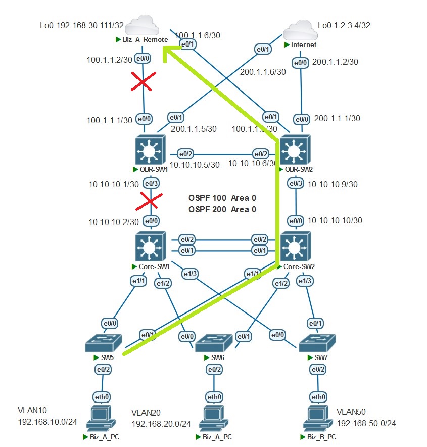
大概思路思路是通过 Track 关联降低 VRRP 的优先级使其成为 VRRP 的 Backup 组,流量路径自动切换至另一台设备。举个例子:当 Core-SW1 以出接口 e0/0 监测到与 OBR-SW1 直连线路不通或监测到 Biz_A_Remote 的 e0/0 不通(这是个 and 的关系,用编程语言的描述就是:条件 A 和条件 B 同时为 True,结果才为 True),此时 SLA 监测状态为 Time-out ,在 VRRP 与 Track 联动下降低 VRRP 优先级使其成为 Backup 状态,Biz_A_PC 去往 Biz_A_Remote 的流量路径切换至 Core-SW2 ,途径:Core-SW2 –> OBR-SW2 最终到达 Biz_A_Remote ,如图所示:
Ending
- 总算码完了,其实还挺耗时间的写文章,但是对做拓扑实验做了梳理,其中还包含怎么清晰的表达我的思路和想表达的意思。
- 配置存阿里云盘了,这是链接:[分享的文件 ]
- 欢迎“
来电”来函探讨。 - 下一篇文更有意思^_^,To be continued.